Practical Guide to Getting Started with the TS-7250-V3
Introduction
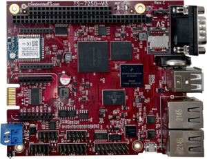
This guide intends to help you quickly and easily get the TS-7250-V3 up and running; the following guide provides a more casual step-by-step approach for setting up everyday connections, networking, and environments to begin development.
The official manual contains more detailed and advanced information if you want to dig deeper into the specifications.
Connections
The connections most commonly used for development are serial console, power, and Ethernet. An optional chip that delivers WiFi/Bluetooth connectivity (with a u.FL Antenna) is also available; this chip is part of the development package but is a special request for the standard package.
Serial Console
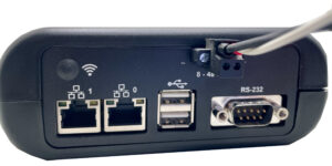
The serial console allows direct access to the embedded system device and is generally the most reliable. The TS-7250-V3 has two separate options for connecting to the serial: the DB-9 port via the enclosure (“RS-232”) or the micro USB connector inside the enclosure. As a side note, the DB-9 port might require a separate adapter if there is no serial port on your workstation.
The DB9 port uses 115200 baud 8n1 with no flow control. The built-in USB serial device is hard coded to the correct baud/mode and does not require configuration.
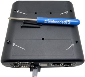
To access the micro USB inside the enclosure: flip the enclosure over and remove the four screws on the bottom. Pull the enclosure apart; on the inside, there will be four more screws on the device to remove for access to the micro USB.

Until power is connected, the console window will be black. The device will output information via console once power is connected.
The preference is always to use Linux OS for our products, though the official manual contains all the information necessary to connect to the console on any OS.
Your serial device name will depend on the OS used, but the typical names to expect are
- Linux: /dev/ttyACM0
- The Linux device number might change based on the number of devices connected to the system.
- Mac OSX: /dev/tty.usbmodem00D069C0FFEE1
- The MAC address determines the Mac OSX device number; it will be different for every device.
- Windows: use Device Manager to discover the COM port
Power
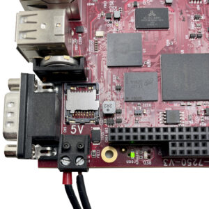
The TS-7250-V3 accepts power two ways: variable input voltage between 8 to 28 VDC via the enclosure and fixed input voltage of 5 VDC inside the enclosure. Only connect to one power source at a time.
Ethernet
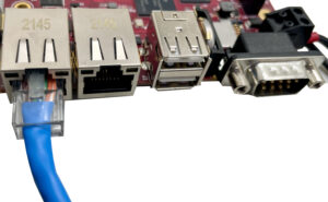
For network access, the device supports two independent Ethernet ports, eth0 (or end0) and eth1 (or end1), both labeled on the outside of—and accessible via—the enclosure. These ports will fit a standard Ethernet cable; connect the other end to a router or switch and continue reading for setup instructions.
Wireless Module (Optional)
The development kit includes an optional wireless module. This module is otherwise available by request for other kits, such as the standard kit.
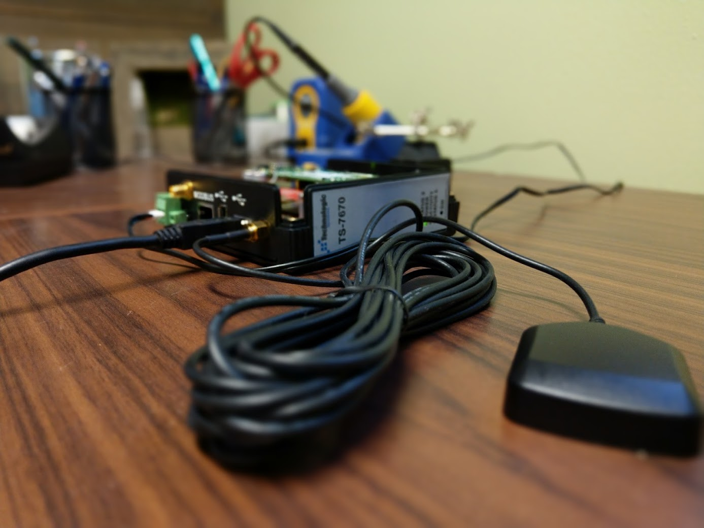
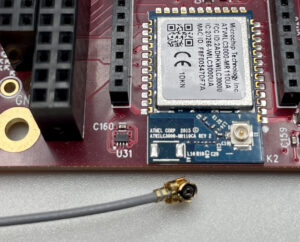
The wireless module requires a separate u.FL Antenna and can be ordered through embeddedTS. Carefully plug the antenna into the available port on the WiFi chip, accessible within the enclosure.
The wireless module allows easy updating of your device over a WiFi connection. We will cover the basics of setting up networking over WiFi further down. For more detailed information on setting up the WiFi module, start at the “Networking” section of the manual.
First Linux Boot
With serial and power applied, the TS-7250-V3 will by default boot to the Embedded MultiMedia Card (eMMC), which is pre-programmed to load our default Debian 12 – Bookworm image. Once this version of Linux loads, it will ask the user to log in with their username and password.
The default password is “root” with no password. You can change this any time after logging in by using the command “passwd” to set an account password.
About the Embedded Linux Environments
The TS-7250-V3 can boot to several different operating systems and environments via U-Boot, a preinstalled bootloader on the device. U-Boot is installed in the eMMC hardware boot partition and can be customized to boot images from the microSD, eMMC, NFS, or USB.
By default, U-Boot will look for a USB mass storage device before using the pre-programmed eMMC with our Debian 12 image. For U-Boot commands, both basic and advanced, see the “U-Boot” section of the manual.
As mentioned, the TS-7250-V3 will automatically boot our Debian 12 – Bookworm image unless configured otherwise. More detailed and advanced information is available in the “Debian 12 – Bookworm” section of the manual. The rest of this guide uses Debian 12 commands.
A new addition to Debian 12, relevant for the next section, is that network interfaces now follow predictable network interface names; eth0 and eth1 are no longer the default for Ethernet connections. You can find a thorough explanation for the new network naming here, but this guide will cover the basics of getting set up with the new naming schemes.
(If booting from an older version of Debian, you can refer back to the “Debian 11 – Bullseye” section of the manual for examples using the older naming scheme, such as eth0 and eth1, for Ethernet connections.)
Networking Set Up
The TS-7250-V3 allows both wired and wireless methods to connect to a network. This section will walk you through how to set up Ethernet or Wireless connections, get an IP address dynamically or statically, and, using WiFi, connect to various types of access points.
Full details are available in the “Debian 12 – Networking” section of the manual. As mentioned above, Debian 12 uses new naming schemes; generally, eth0 is now end0 and eth1 is now end1.
To start, in your console, list network interfaces by running
ip addr show
The most common network interfaces are
- end0 – Ethernet device 0 (CPU Ethernet)
- enp1s0 – Ethernet PCIe port 1 slot 0 ethernet
- usb<mac> – USB ethernet
- wlan0 – WIFI
Pro-Tip: The interface marked as “1” on the enclosure (reference designator “T2” on the PCB silkscreen) is end0; the interface marked as “0” on the enclosure (reference designator “T1” on the PCB silkscreen) is end1.
Wired
The Debian networking wiki has more advanced details, such as adding IPv6 to dynamic or static IP setups. The steps below also apply to end1 if you want to use both Ethernet ports.
Dynamic IP
Getting an IP via DHCP is convenient for most applications.
In your console of choice, edit the file
/etc/network/interfaces
go to the bottom of the file and paste
auto end0
iface end0 inet dhcp
These commands will enable the end0 network interface and allow the device to get an IP address dynamically; both will happen automatically on future boots.
Any changes made will take effect on the next boot; you can also manually cycle the network interface to apply the changes with
ifdown end0
ifup end0
Double-check the connection information on the next boot by using the ifconfig command. The example device was assigned a dynamic IP of 10.10.10.193.
root@tsimx6ul:~# ifconfig
end0: flags=4163<UP,BROADCAST,RUNNING,MULTICAST> mtu 1500
inet 10.10.10.193 netmask 255.255.255.0 broadcast 10.10.10.255
inet6 fe80::ea1a:58ff:fe00:60d5 prefixlen 64 scopeid 0x20<link>
ether e8:1a:58:00:60:d5 txqueuelen 1000 (Ethernet)
RX packets 332 bytes 28642 (27.9 KiB)
RX errors 0 dropped 0 overruns 0 frame 0
TX packets 54 bytes 4644 (4.5 KiB)
TX errors 0 dropped 0 overruns 0 carrier 0 collisions 0
lo: flags=73<UP,LOOPBACK,RUNNING> mtu 65536
inet 127.0.0.1 netmask 255.0.0.0
inet6 ::1 prefixlen 128 scopeid 0x10<host>
loop txqueuelen 1000 (Local Loopback)
RX packets 3968 bytes 309280 (302.0 KiB)
RX errors 0 dropped 0 overruns 0 frame 0
TX packets 3968 bytes 309280 (302.0 KiB)
TX errors 0 dropped 0 overruns 0 carrier 0 collisions 0
The device can now ping an external URL to test the connection.
root@tsimx6ul:~# ping debian.org
PING debian.org (151.101.194.132) 56(84) bytes of data.
64 bytes from 151.101.194.132 (151.101.194.132): icmp_seq=1 ttl=59 time=4.29 ms
64 bytes from 151.101.194.132 (151.101.194.132): icmp_seq=2 ttl=59 time=3.62 ms
64 bytes from 151.101.194.132 (151.101.194.132): icmp_seq=3 ttl=59 time=7.25 ms
64 bytes from 151.101.194.132 (151.101.194.132): icmp_seq=4 ttl=59 time=3.63 ms
64 bytes from 151.101.194.132 (151.101.194.132): icmp_seq=5 ttl=59 time=3.78 ms
64 bytes from 151.101.194.132 (151.101.194.132): icmp_seq=6 ttl=59 time=6.99 ms
^C
— debian.org ping statistics —
6 packets transmitted, 6 received, 0% packet loss, time 5014ms
rtt min/avg/max/mdev = 3.619/4.926/7.245/1.565 ms
Static IP
The static IP setup is similar to the dynamic IP setup from above.
In your console of choice, edit the file
/etc/network/interfaces
go to the bottom of the file and paste
auto end0
iface end0 inet static
address 192.0.2.7/24
gateway 192.0.2.254
These commands will enable the end0 network interface and force the device into the assigned IP; both will happen automatically on future boots.
Any changes made will take effect on the next boot; you can also manually cycle the network interface to apply the changes with
ifdown end0
ifup end0
Double-check the connection information on the next boot by using the ifconfig command. The example device was assigned a static IP of 192.0.2.7.
root@tsimx6ul:~# ifconfig
end0: flags=4163<UP,BROADCAST,RUNNING,MULTICAST> mtu 1500
inet 192.0.2.7 netmask 255.255.255.0 broadcast 0.0.0.0
inet6 fe80::ea1a:58ff:fe00:60d5 prefixlen 64 scopeid 0x20<link>
ether e8:1a:58:00:60:d5 txqueuelen 1000 (Ethernet)
RX packets 2989 bytes 243473 (237.7 KiB)
RX errors 0 dropped 0 overruns 0 frame 0
TX packets 107 bytes 7648 (7.4 KiB)
TX errors 0 dropped 0 overruns 0 carrier 0 collisions 0
lo: flags=73<UP,LOOPBACK,RUNNING> mtu 65536
inet 127.0.0.1 netmask 255.0.0.0
inet6 ::1 prefixlen 128 scopeid 0x10<host>
loop txqueuelen 1000 (Local Loopback)
RX packets 3968 bytes 309280 (302.0 KiB)
RX errors 0 dropped 0 overruns 0 frame 0
TX packets 3968 bytes 309280 (302.0 KiB)
TX errors 0 dropped 0 overruns 0 carrier 0 collisions 0
Test your connection by pinging your gateway, 192.0.2.254. 0% packet loss in the below report means your connection is running as expected.
root@tsimx6ul:~# ping 192.0.2.254
PING 192.0.2.254 (192.0.2.254) 56(84) bytes of data.
64 bytes from 192.0.2.254: icmp_seq=1 ttl=64 time=6.80 ms
64 bytes from 192.0.2.254: icmp_seq=2 ttl=64 time=3.81 ms
64 bytes from 192.0.2.254: icmp_seq=3 ttl=64 time=3.62 ms
^C
— 192.0.2.254 ping statistics —
3 packets transmitted, 3 received, 0% packet loss, time 2007ms
rtt min/avg/max/mdev = 3.621/4.741/6.797/1.455 ms
Wireless (Optional)
The wireless section only applies if you have ordered the development package or have requested the optional wireless module. Please make sure the u.FL antenna is attached.
This part of the guide will cover setting up a protected access point, which works for WPA and WPA2. It will be utilizing the wpasupplicant utility. For more detailed information on WiFi configurations, see the Debian guide on how to use WiFi.
If you want to use the TS-7250-V3 as a Wireless Access Point, see the “WiFi Access Point” section of the official manual.
Important note: embeddedTS includes many applications in the Debian 12 image that are useful. The instructions below should work seamlessly; however, if you have issues getting WiFi to work correctly, install “wpasupplicant” using your console of choice.
Install wpasupplicant
apt-get update && apt-get install wpasupplicant -y
Protected Access Point
Scan for available access points using
iwlist wlan0 scan
or filter so only the essid names are visible by using
iwlist wlan0 scan | grep ESSID | cut -d’:’ -f2
Once you know the protected network you want to connect to, run
wpa_passphrase yourssid yourpassword
The command output will look similar to the text below but contain your personalized information.
network={
ssid=”yourssid”
#psk=”yourpassword”
psk=151790fab3bf3a1751a269618491b54984e192aa19319fc667397d45ec8dee5b
}
Use the hashed pre-shared key (PSK) in the specific network interface file for added security.
In your console of choice, edit the file
/etc/network/interfaces
go to the bottom of the file and paste
allow-hotplug wlan0
iface wlan0 inet dhcp
wpa-ssid yourssid
wpa-psk 151790fab3bf3a1751a269618491b54984e192aa19319fc667397d45ec8dee5b
Be sure to edit “yourssid” with your ssid and the PSK characters with the PSK output you received when you ran wpa_passphrase.
In the text above, allow-hotplug wlan0 makes the WiFi connection persistent upon rebooting the device; iface wlan0 inet dhcp automatically assigns a dynamic IP.
Any changes made will take effect on the next boot; you can also manually cycle the network interface to apply the changes with
ifdown wlan0
ifup wlan0
Conclusion
The Practical Guide to Getting Started with the TS-7250-V3 covered the available ways to connect to the console for communication with the device, apply power, and set up Ethernet and WiFi networking. These will allow you to begin development on your application.
The official manual will fill in the blanks for other advanced information.
Did the TS-7250-V3 Getting Started Guide miss anything? Comment below so we can get it added!